EXAMPLE 3 – HYDROGEN VENTILATION USING LOW VENTS AND RISER TUBE
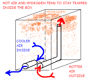
A battery enclosure using low vents and a riser tube is shown in Figure 3A & 3B. This type of ventilation system makes an attempt to use the properties of natural convection as described in Example 2. Placement of the inlet and outlet vent tubes at the same height (low on the wall) prevents some of the unwanted thermal convection described in Example 2 which causes too much air flow and excessive temperature extremes inside the box.
Since Hydrogen tends to rise inside the box, this system works against the natural forces at work in the battery box. A high vent is really needed to effectively remove hydrogen from the top of the box by natural convection.
Hydrogen Ventilation Using Low Vents and Riser Tube, Cold Day Convection Trap.
Figure 3A shows that on a cool day, the lighter warm air and lighter Hydrogen will rise together to the top of the box and be trapped there creating a very dangerous explosion hazard. Natural diffusion of the hydrogen will cause it to mix with the air throughout the box. Neither the warm air nor the light-density hydrogen gas will sink down the riser tube by natural convection.
FIGURE 3B
Hydrogen Ventilation Using Low Vents and Riser Tube, Warm Day Hydrogen Trap.
Figure 3B shows that on a warm day, when the inside temperature is cooler than outside, air flow through the vents may occur, driven entirely by the temperature difference between the inside and outside air. The Hydrogen will tend to rise and be trapped in the top of the box. Natural diffusion will spread the hydrogen throughout the box and the airflow on a warm day may dilute it, but not with any reliability or efficiency. Under the right conditions, this system can cause explosive levels to be reached inside the box.


